Check for tub moving freely by hand and if does not may it be a bad clutch assembly.
Check for a foreign item between the tubs.
If it does move freely check for cracked magnets on the rotor. The stator windings may have resistance values outside of specification you will need to use a meter to check the stator.
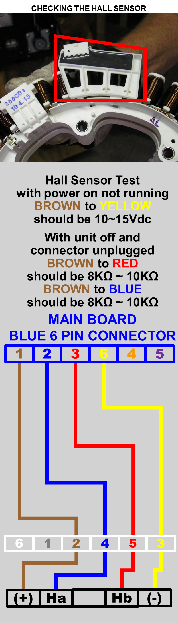
Some models have a hall sensor that will cause this error code if the hall sensor is defective. Check it for proper resistance and voltage.
Before each Hall Sensor wiring diagram in this article is a list of models. Be sure you are on the correct wiring diagram for your model.
DETAILS BELOW:
If tub does not rotate in wash cycle, spin tub by hand. Does tub make a noise?
If noise is present unplug the unit and turn onto its side for visual inspection.
Check the Rotor bolt and Stator bolts for tightness.
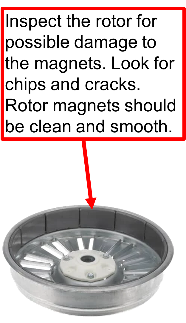
Inspect rotor, clutch and coupler assemblies for possible damage.
Check Stator harness for damage.
If no noise is being produced then inspect hall sensor & stator wire harness connectors for tightness.
Inspect Rotor Magnets for damage.
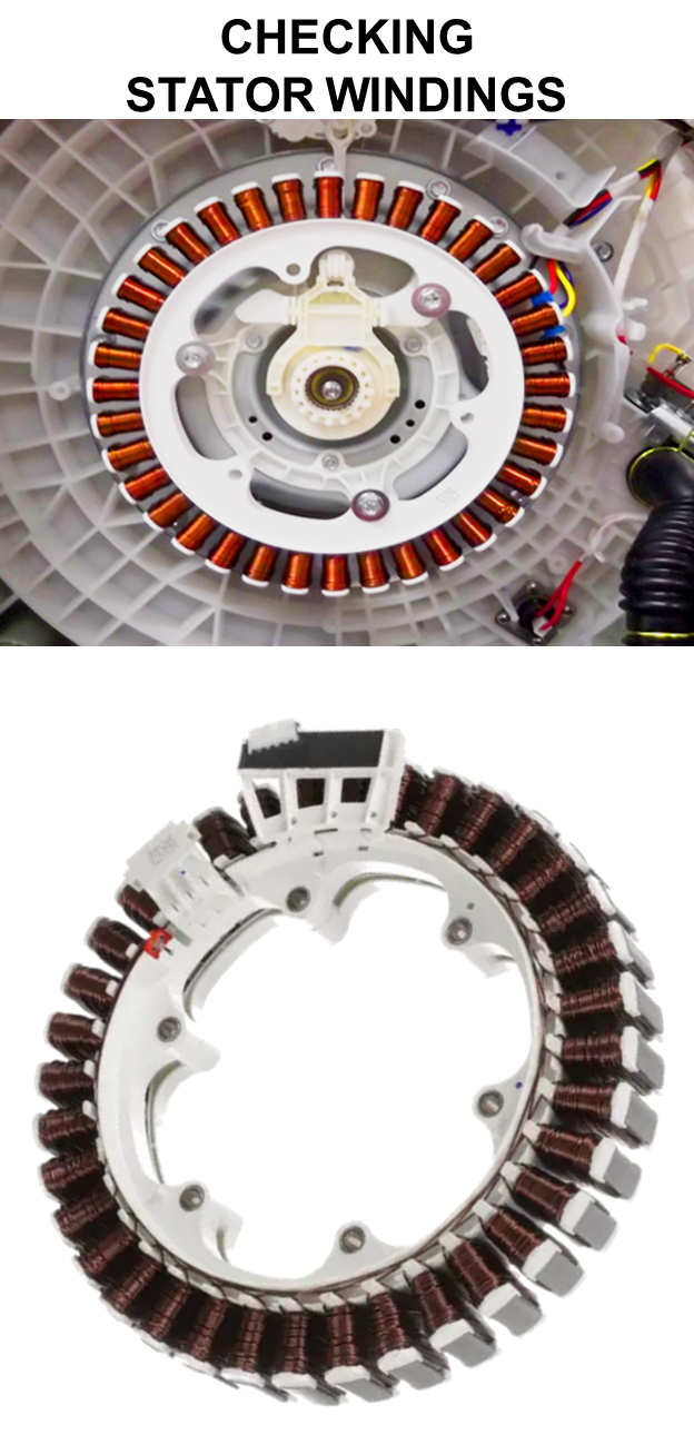
CHECK STATOR WINDINGS
RESISTANCE VALUES
The resistance values should be greater than 5 ohms and less than 15 ohms on each winding. All windings within ± 1 ohm of each other.
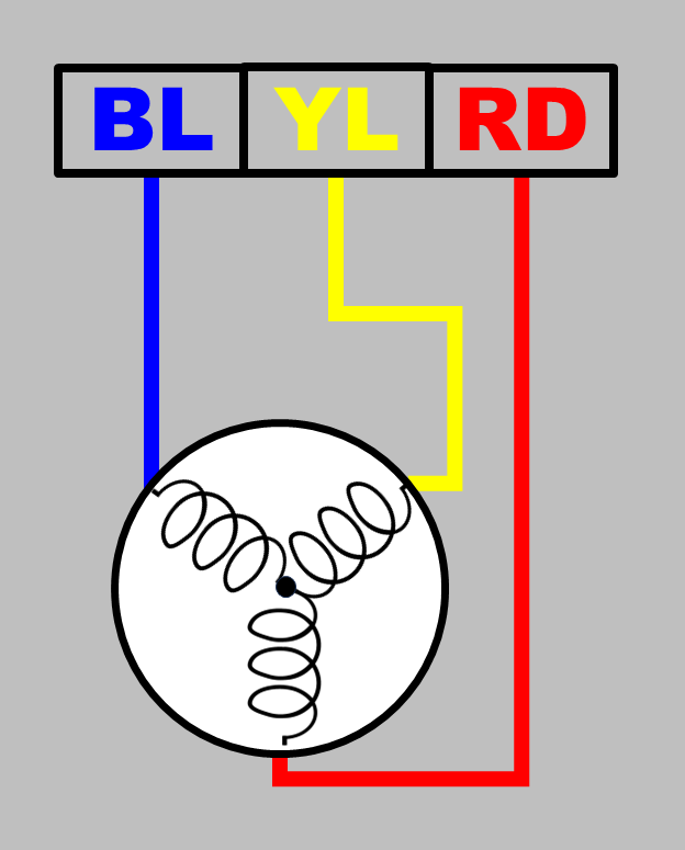
EXAMPLE READINGS:
BLUE to YELLOW = 10 OHMS
BLUE to RED = 11 OHMS
RED to YELLOW = 10.4 OHMS
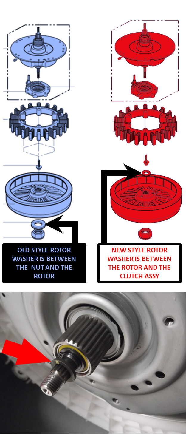
Some models have a special recess for a washer that has to be installed or unit will NOT agitate properly and may cause a LE error code. Check for this issue.
If you need to know what style you have check the exploded view for this information.
This style of Top Load Washer is newer than the style that has the washer on the outside of the rotor. See examples below.
BELOW IS THE WIRING DIAGRAM LAYOUT FOR THE HALL SENSOR FOR THE FOLLOWING MODELS:
WT1001, WT1101, WT1201
WT1701NOT WT1701/01
BELOW IS THE WIRING DIAGRAM LAYOUT FOR THE HALL SENSOR FOR THE FOLLOWING MODELS:
WT4801, WT4870, WT4901,
WT4970, WT5070, WT5075,
WT5170,
WT5480, NOT WT5480/01
WT5680, NOT WT5680/01
WT6001
BELOW IS THE WIRING DIAGRAM LAYOUT FOR THE HALL SENSOR FOR THE FOLLOWING MODELS:
WT5001, WT5101
THE FOLLOWING MODELS DO NOTHAVE A HALL SENSOR. YOU CAN VERIFY BY LOOKING AT THE STATOR AND YOU WILL NOT SEE THE HALL SENSOR PART ATTACHED TO THE STATOR.