1.) Is the drawer fully closing?
2.) Is the drawer warped or misaligned?
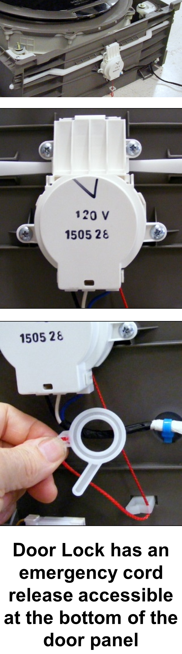
3.) Is the door lock installed correctly?
4.) Are the locking arms mechanically binding?
5.) Unplug the unit. Check the harness connections at the door lock
motor and Main PCB.
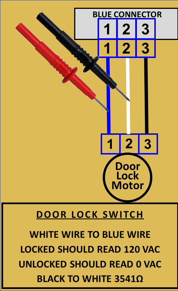
6.) Locate connector BL3 on the Main PCB and unplug. Check the
resistance of the door lock motor from Black to White. The resistance
should be approximately 3.5k ohms. If an open is read, check the
resistance at the door lock motor. If still open, replace the door lock
motor. If resistance is okay, suspect a wiring harness issue.
7.) Reconnect connector BL3. Plug in the unit. Start a cycle and measure
the voltage from Black to White. If no voltage is present replace the
Main PCB. If voltage is present, check voltage at the door lock motor.
If no voltage is present, suspect a harness issue. If voltage is present but
motor not working, replace the motor.
8.) Signal test. When the motor is working, there should be a momentary 120Vac voltage from the door lock motor returned to the Main PCB. Measure this voltage on BL3 from Blue to White. If voltage is not present, check the voltage out of the motor. If not voltage is present replace the door lock motor. If voltage is present, suspect a harness issue. If the signal voltage is present at BL3, replace the Main PCB. If the harness needs to be replaced it is part location M031. The door lock motor is part location M029.