No heat issue. This is displayed when a temperature rise is not seen and the unit stops with 9A5 in the display.
Solution
Check the gas suppled to the unit to insure the customer gas supply valve is turned on.
Solution
Check the ignition circuit for possible bad igniter, flame switch, gap between igniter and flame holder.
Also check for 120 volts ac to the igniter, and at least 90 Vdc to both gas valves.
DETAILS BELOW:
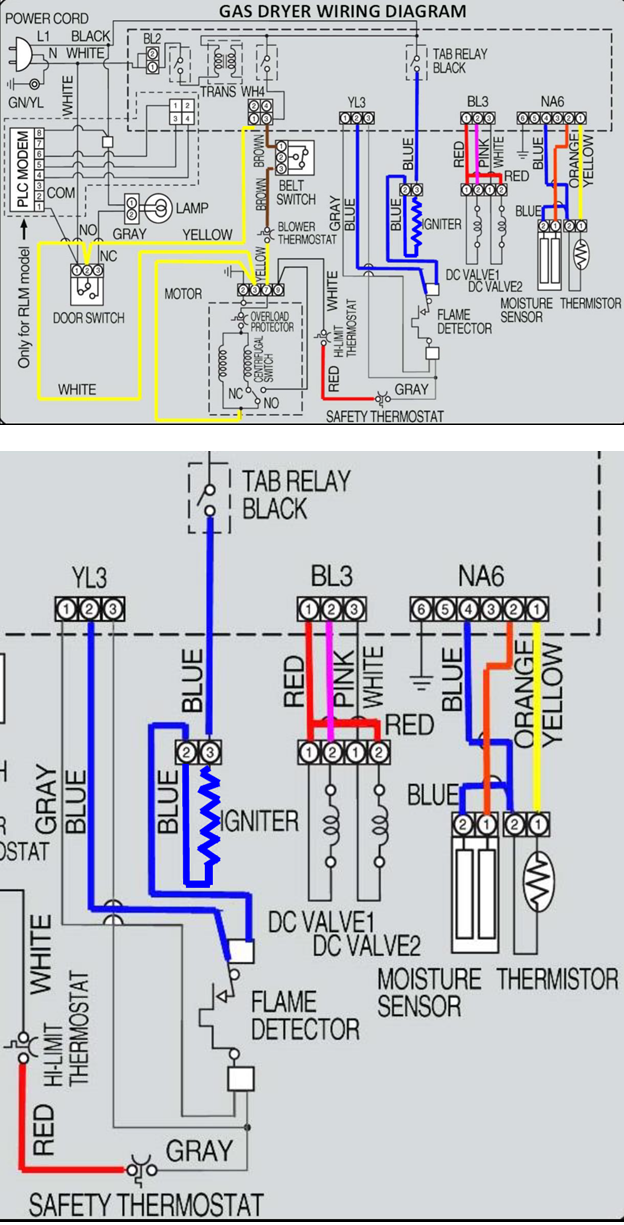
Gas Dryer Ignition Steps
To get gas ignition the dryer motor turns and the main board performs 3 tasks.
1) Closes the Black Relay to place the L1 side of the 120 VAC on blue wire to igniter.
2) Verifies Flame Detector Switch is closed using YL3, pins 1 & 2, GRAY & BLUE wires.
3) Places >90 VDC on DC Valve 1 (BL3, pins 1 & 2, Red to Pink) of the gas valve.
Following the successful completion of tasks 1 & 2, current will begin to flow through the igniter circuit. The radiant heat from the igniter will reach sufficient temperature to open the normally closed flame detector switch. (The opening temperature for the flame detector is approximately 370ºF.) With the flame switch open the GRAY & BLUE wires from YL3, pins 1 & 2 to the Flame Detector Switch are seeing 120 VAC across the open flame detector. When the flame detector switch opens, the main control board will next place >90 VDC on DC Valve 2 (BL3, pins 1 & 3, Red to White) of the gas valve assembly. With both gas valve solenoids energized regulated gas pressure is allowed to flow through the valve, mix with the primary air, and is ignited by the still glowing igniter. The radiant heat from the burner maintains the Flame Detector Switch in an OPEN condition, keeping 120 VAC across YL3 pins 1 & 2, BLUE to GRAY;
this is the flame proving circuit.
As the exhaust temperature rises and the exhaust temperature sensor measures this temperature increase, the control board will remove the >90 VDC on both gas burner valve solenoids when the set point for the selected cycle reaches the designed temperature; the gas valve turns off. Simultaneously, the control board will cycle OFF the igniter circuit by opening the Black Tap Relay.
IF ignition fails to occur, the black tap relay remains closed, the flame detector switch cools & closes at its closing temperature (approximately 320ºF) thereby removing the 120 VAC across YL3 pins 1 & 2. When the flame detector switch closes, the control board removes the >90 VDC to DC Valve 2, stopping gas flow through the valve.(Note: The control board continues to apply >90 VDC to DC Valve 1)
With the flame detector switch closed, the igniter again heats and the radiant heat from the igniter opens the flame detector switch placing 120 VAC on YL3, pins 1 & 2, BL to GY. The control again applies >90 VDC to DC Valve 2. This allows fuel flow through the gas valve in a 2nd attempt to ignite the fuel / air mixture. The Flame detector switch and YL3 pins 1 & 2 allows the control board to know IF ignition has taken place when the burners’ radiant heat following ignition maintains the Flame Detector in an OPEN condition and 120 VAC is measured across YL3 pins 1 & 2, BL to GY. With failed ignition these steps are repeated again and again until ignition takes place. A common failure has been the DC Valve 1 solenoid.
If the flame detector switch fails open or if the BL & GY wires from YL3, pins 1 & 2 break, or if the YL3 connector is disconnected at the control board, the control board will not apply DC voltage to either gas valve solenoid.
Igniter Circuit:
The neutral side of the line to the igniter travels via the white wire from the line cord, through the closed door switch pins 1 to 2 to motor terminal pin 3. In the motor neutral passes through the centrifugal switch to motor pin 9. From pin 9 of the motor switch neutral continues on a white wire to the Hi-Limit Thermostat, exits on the red wire to the Safety Thermostat, and from there leaves on a GY wire to the Flame Detector Switch. Finally, neutral leaves the Flame detector switch on a blue wire to the Igniter. Reminder: If the flame detector switch is open due to failure, that is 120 VAC is measured across YL3, pins 1 & 2 after the Black Tap Relay closes, the control board will not energize the gas valve solenoids with DC voltage. This becomes the safety proving circuit.
L1 enters the Black Tap Relay on a Black wire and exits the relay on a Blue wire to the Igniter. With L1 & Neutral present on the igniter (120 VAC), amperage increases as igniter resistance decreases.
The measured amperage reaches approximately 4 amps when ignition takes place.
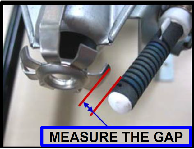
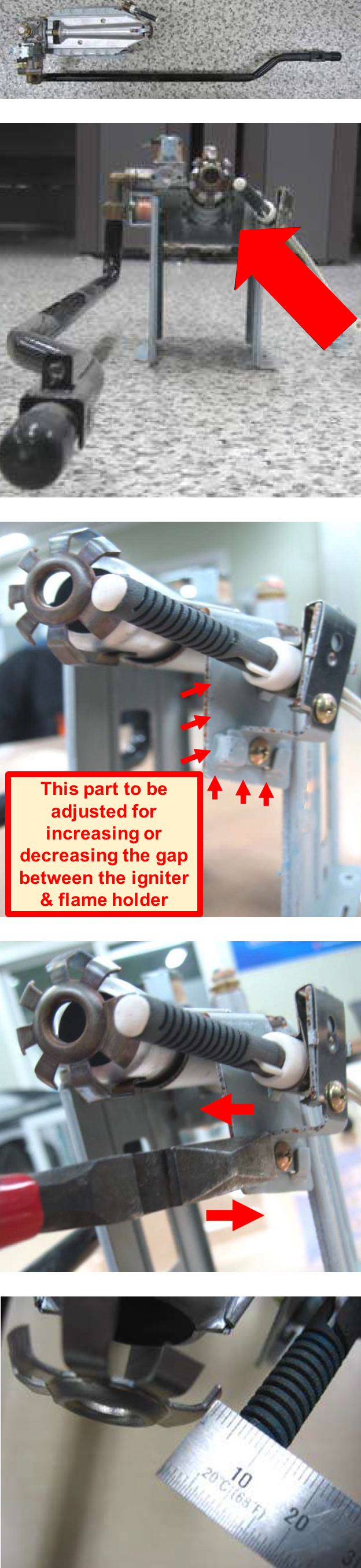
The distance between the igniter & flame holder should be between 3mm and 6mm
(1/8 – 1/4 inch)
If the distance is not within this range, adjust it.
ADJUSTINGTHE GAP
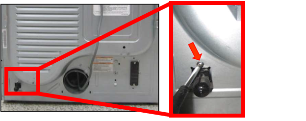
Step1. disassemble the dryer
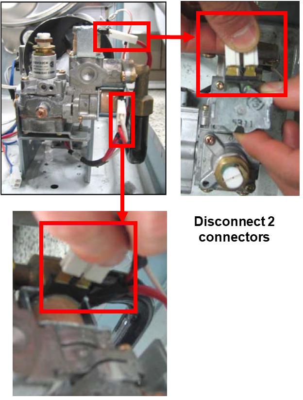
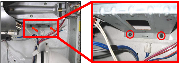
Step2. disassemble the burner assembly
Remove 2 screws as shown below
Remove 1 screw on back of dryer
Now disassemble the burner assembly by keeping it tilted and pushing it as shown in the pictures. Push to release it from the clamp at the base.
Great info but need to add when a gas regulator is needed. Ive seen ignition failure is fue to high gas pressures. Once customer installs a regulator behind unit then unit ignited properly everytime. Many techs facing this issue and replacing high unecessary parts with no resolution.
We suggest in the troubleshooting for techs to always check the customer’s incoming gas pressure to eliminate guessing what is wrong with the unit.
Most techs do not use a gas pressure gauge so they just start changing all parts.
You can also suggest to the customer to have the gas company to check their gas pressure for them and to have them adjust or install a separate regulator before changing parts.
On some occasions I have had that error code, the failure was caused by too much gas pressure, these devices if they detect very little pressure or too high the pressure will not ignite the flame, it must be in a range of 6oz in2 to 8oz in2 ( LP gas), greetings, I hope it helps you. atte. ing Miranda, Chetumal, Quintana Roo.


3 Responses
Great info but need to add when a gas regulator is needed. Ive seen ignition failure is fue to high gas pressures. Once customer installs a regulator behind unit then unit ignited properly everytime. Many techs facing this issue and replacing high unecessary parts with no resolution.
We suggest in the troubleshooting for techs to always check the customer’s incoming gas pressure to eliminate guessing what is wrong with the unit.
Most techs do not use a gas pressure gauge so they just start changing all parts.
You can also suggest to the customer to have the gas company to check their gas pressure for them and to have them adjust or install a separate regulator before changing parts.
On some occasions I have had that error code, the failure was caused by too much gas pressure, these devices if they detect very little pressure or too high the pressure will not ignite the flame, it must be in a range of 6oz in2 to 8oz in2 ( LP gas), greetings, I hope it helps you. atte. ing Miranda, Chetumal, Quintana Roo.