Main board does not detect that the Door Lock switch is closed.
Main board missing the 120VAC on the BLACK wire of the Door Lock Monitor Circuitry.
Solution
Make sure that the door is closed properly.
Check for warped or misaligned door.
Loose connection at the Main board or door switch.
Bad door Switch.
Bad Main Board.
The washer will not operate unless the lid is locked.
Inspect the door strike for damage. Check for improper alignment of the door causing alignment issues with the strike and door lock.
DETAILS BELOW:
DRYER
DOOR LOCK
METER
READINGS
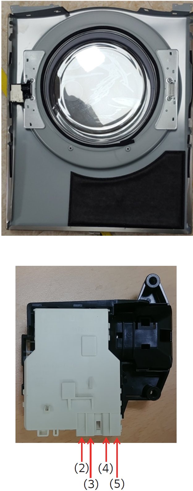
TERMINAL
2 TO 4
0.7KΩ
–
1.5KΩ
TERMINAL
3 TO 4
60Ω –
90Ω
TERMINAL
4
TO 5
INFINITE
/
OPEN READING
SOME NEW LG DRYERS ESPECIALLY THE CONDENSING DRYERS WILL USE THIS STYLE OF LOCK JUST LIKE THE LOCK ON THE FRONT LOAD WASHERS.
USE THE INFORMATION BELOW AND PAY ATTENTION TO THE DOOR LOCK PIN NUMBERS BECAUSE THE WIRING COLORS MAY VARY ON EACH MODEL.
The door lock solenoid 120Vac is activated by pin 4 ORANGE wire to pin 3 BLACK wire.
The door switch makes / breaks L1 side of the neutral line pin 2 RED wire to pin 1 BLACK wire.
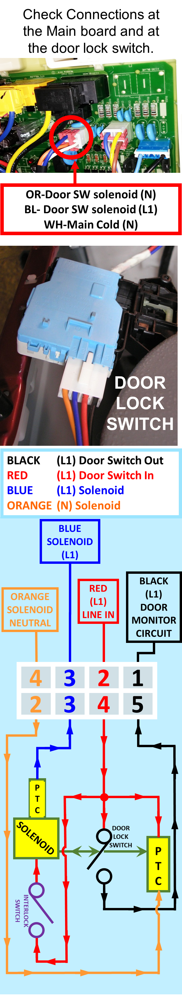
NOTE: Interlock switch is closed by door locker when door is closed!
Door must be closed to complete the circuit to the door lock solenoid.
THEORY OF OPERATION
Step 1 – When the POWER Button is pressed 120VAC will be measured from ORANGE (N) to RED (L1).
Step 2 – When the Door is closed the 120VAC from the RED (L1) will travel through the closed interlock switch, solenoid, PTC and leave on the BLUE wire to the BLUE wire on the WHITE Connector on the Main board. This 120VAC will satisfy the Door Close Monitor Circuit & prevent a dE1 error code.
Step 3 – When the customer selects the cycle, options and presses the start button the Main board will send 120VAC variable frequency pulses between the ORANGE (N) & BLUE (L1).
Step 4 – This variable frequency pulse will energize the door lock solenoid and close the Door Lock Switch.
Step 5 – L1 from RED will travel through the Door Lock Switch, exit the BLACK wire and will go to the Door Lock Monitor circuit on the Main board The 120VAC on the BLACK wire will be monitored by the Door Lock Monitor Circuitry, satisfy the Microcomputer on the Main board and the cycle selected will begin!
If the Main board does not see the 120VAC on the BLACK wire, a dE2 error code will be displayed and the cycle will not start!