dE DOOR OPEN ERROR
Cause
Main Board is not seeing a closed Interlock Switch from the Door Switch.
Solution
Make sure that the door is closed properly.
Check for warped or misaligned door.
Loose connection at the Main board or door switch.
Bad door Switch
Bad Main Board.
The washer will not operate unless the lid is locked.
“dE” error code may be a bad drain pump with winding readings falling below normal readings. Check drain pump for resistance values good reading 10~20ohms, bad reading 0.8~3ohms.
If the supplied 120Vac from customer’s power receptacle goes below 120Vac it can also cause the “dE” error code.
Check to be sure the power cord is firmly plugged into the receptacle and that the customer’s receptacle is not loose.
DETAILS BELOW:
The following information is for LG Front Load Washers with a manufacturer production date of 2009 or newer.
If you are working on a 2008 or older LG Front Load Washer the only difference is the polarity is reversed on the diagram and following information. Every reference to 120Vac (L1) will be Neutral (N) and every reference to Neutral (N) will be a 120Vac (L1).
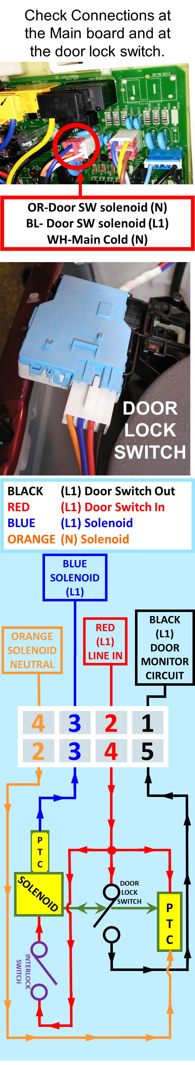
The door lock solenoid 120Vac is activated by pin 4 ORANGE wire to pin 3 BLACK wire.
The door switch makes / breaks L1 side of the neutral line pin 2 RED wire to pin 1 BLACK wire.
NOTE: Interlock switch is closed by door locker when door is closed!
Door must be closed to complete the circuit to the door lock solenoid.
THEORY OF OPERATION
Step 1 – When the POWER Button is pressed 120VAC will be measured from ORANGE (N) to RED (L1).
Step 2 – When the Door is closed the 120VAC potential from the RED (L1) will travel through the closed interlock switch, solenoid, PTC and leave on the BLUE wire to the BLUE wire on the WHITE Connector on the Main board. This L1 potential will satisfy the Door Close Monitor & prevent a dE1 error code.
Step 3 – When the customer selects the cycle, options and presses the start button the Main board will send 120VAC variable frequency pulses between the ORANGE (N) & BLUE (L1).
Step 4 – This variable frequency pulse will energize the door lock solenoid and close the Door Lock Switch.
Step 5 – L1 from RED will travel through the Door Lock Switch, exit the BLACK wire and will go to the Door Lock Monitor circuit on the Main board The 120VAC on the BLACK wire will be monitored by the Door Lock Monitor Circuitry, satisfy the Microcomputer on the Main board and the cycle selected will begin!
If the Main board does not see the 120VAC on the BLACK wire, a dE2 error code will be displayed and the cycle will not start!
One Response
This is very helpful side